• The First Square Wave Oscillator

    Andrzej Arszulowicz • 09/23/2026 at 09:54 • 0 comments

    The first square wave oscillator

    This was my first step into analog synth creation. I believe I had just seen a video from Moritz Klein on one of my social media feeds about a simple kick drum made with an op amp and a few caps and resistors. This resonated with me, as around that time my class was learning about operational amplifiers with feedback and their multitude of uses. I wondered if there was a similarly simple way to create a continuous tone generator, so I had a quick search online. To my delight I found instructions for a bare-bones square wave generator using the components I already had in my student lab kit. It uses just 5 components; 3 resistors, a capacitor and an op amp. Here is a schematic I re-created:

    Figure 1: simple square wave generator

    This is likely the simplest possible oscillator that can be constructed and there are many, many videos and articles detailing it. However, I am going to try to explain in my own words how it works.

    The circuit is switched on. There will always be some noise in the circuitry and surroundings that will cause one of the inputs to be slightly higher than the other. Let us assume it is the non-inverting input, although the same process happens if it happens to be the inverting input, just π radians out of phase.

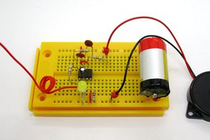
    Due to the op-amp’s very high open loop gain, V_Out will slam to the positive rail. The resistors R1 and R2 now form a voltage divider between V_Out and ground, and the voltage at the non-inverting input can be calculated as VOut R1R1 + R2. At the same time, V_Out feeds back to the inverting input through R3, and begins charging the capacitor C1. Since the capacitor and the inverting input share a node, the voltage at the input will begin to creep up at the same rate that the capacitor is charging. Once the voltage at the inverting input reaches the voltage at the non-inverting (the threshold voltage), any further minute increase will cause the output of the op-amp to slam to the negative rail, as the voltage at the inverting input is higher than that of the non-inverting. Once this happens, the threshold voltage will flip in polarity and become negative. At the same time, the charged capacitor now begins discharging through R3 until the voltage at the inverting input crosses the now negative threshold voltage, and the output voltage goes high again allowing the process to repeat. And there it is; a square wave oscillator made from just five components. I built this on my breadboard and hooked it up to a speaker and was delighted to hear my creation singing back at me. 

    Immediately I realised that the frequency of this oscillator can be easily varied. One way to do this would be to change the values of the resistors in the positive feedback path that form the voltage divider. By setting the threshold voltage either higher or lower, it alters the time required for the voltage at the inverting input to reach it, influencing the time period of the whole oscillation.

    Another way would be to change the value of the capacitor. A higher capacitance would cause a longer charging time, which again increases the time period and vice versa for a lower capacitance.

    However, I prefer to leave the positive feedback resistors constant and equal to each-other. This is mainly because it makes any equations easier to handle should they be necessary. Also, variable capacitors that fit on breadboards are quite rare and expensive (and I didn’t have one in my lab kit). 

    In my opinion, the neatest and most elegant way to introduce a variable frequency is to swap out the negative feedback resistor, R3, for a variable resistor in the form of a rheostat or a potentiometer with one of its outer legs tied to the inner. This feedback resistor directly influences the time constant of the circuit, RC, by limiting the flow of current that can pass to charge the capacitor plates. Increasing its resistance means it will take longer for the capacitor to charge to the...

    Read more »